Getting Full Performance from
Trickling Filters and CO2 Strippers with the Right Water Distribution System
Trickling filters and CO2 strippers are common devices in recirculating aquaculture systems. They are often referred to as packed towers. The performance of these towers is controlled by:
- The type of packing or media
- The amount of packing
- The shape of the vessel
- The ratio of air to water
- The temperature
- The distribution of air through the tower
- The distribution of water through the tower
The distribution of water is the most commonly neglected and least understood aspect of the design of packed towers. Poor water distribution is often the primary cause for poor performance and high maintenance costs for packed towers. A well designed tower will have an even water distribution across the entire packing surface. For a biofiltration system, this gives all of the microorganisms an equal and consistent supply of nutrients and oxygen. For a stripping tower, even water distribution provides a uniform water film on all of the packing for maximum gas transfer.
Poor water distribution can lead to the following problems:
- Loss of performance due to dry surfaces in the packing bed.
- Loss of performance due to air bypass through the dry areas.
- Erosion of the packing due to locally heavy hydraulic loadings.
- Plugging of the packing due to scale deposits in the intermittently wetted areas
If the water distribution is not done correctly, no other changes will bring the tower up to full performance. On the other hand, improving the water distribution in a tower is a very cost effective way to get more performance out of a system. Although the water distribution system is a key element in the design of a tower, it is a relatively small part of the system cost. Usually, it is less than 10% of the cost. If a distribution system only wets half of the media, the tower must be twice as large to get the same performance as a system that gives complete coverage. It cannot be overemphasized that an even distribution of water is essential to obtain full performance from a packed tower.
Water distribution designs that are less than optimum include the use of the following methods:
- A single pipe that dumps water in the center of the vessel.
- A pipe with a few large holes drilled into the bottom or side.
- A pipe with multiple small holes drilled into the bottom or side.
- A grid or drip plate.
- A system of troughs or launders with notches cut into the edge.
- A single, hollow cone nozzle.
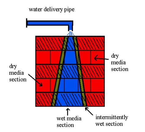
Here is a worse case example. Water is dumped from a pipe at a single point into a vessel.
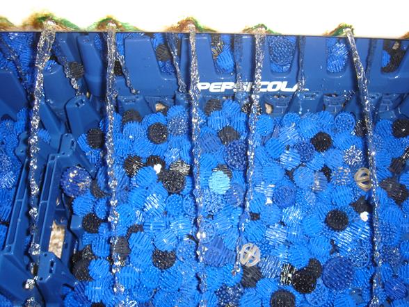
Here is an actual example of a bad water distribution system that we noticed during a tour of a public aquarium. Notice that none of the media is being wetted. Why bother building it?
Spreading the water out evenly doesn't happen by accident or magic. A good water distribution system will typically consist of one of the following three designs:
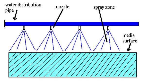
Design 1. - A piping system with square pattern, solid cone spray nozzles. The spray patterns touch at the edges.
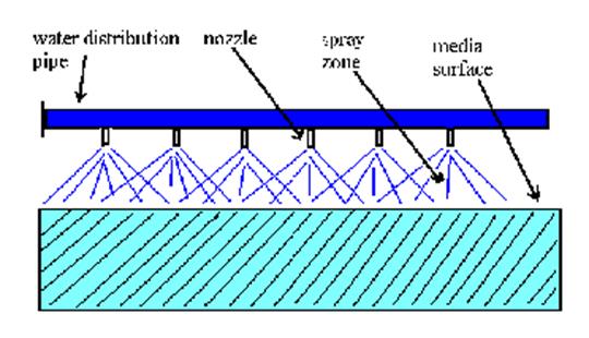
Design 2. - A piping system with round or square hollow cone spray nozzles. The nozzles will be spaced to provide overlapping patterns.
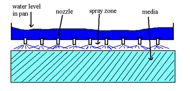
Design 3. - A flat pan or tray holding a few inches of water with target nozzles installed in the bottom. The spray patterns from adjacent nozzles will overlap.
There are advantages and disadvantages for each type of system.
Design 1
This system is simple to design and relatively easy to construct. It can provide even coverage depending on the quality of the spray pattern. The use of a pipe system allows for unrestricted air movement and relatively easy access to the packing media. The main disadvantage is that these systems typically require higher head pressures to operate well. The pressure drop through the nozzles is usually around 5 – 15 ft. of H20.
Design 2
This system is also simple to design and relatively easy to construct. If it is done properly, it will provide a very even water distribution. Head loss will be equal to or less than design 1. The disadvantage of this system is that a larger fraction of the water will impinge on the wall of the vessel. If the vessel is large then this wall fraction will be relatively small. If the vessel is small however, this fraction can be more substantial.
Design 3
This system can be a little more complicated to design due to the structural requirements. The weight of the water in the pan must be well supported. The big advantage to this design is the very low head requirement. Pan type systems can operate with 12" of total head loss. Other disadvantages of this system are the restriction of air flow for counter flow towers and the difficulty of observing or accessing the media.
Nozzle requirements
The ideal nozzle for our applications will have:
1. An even water distribution pattern
2. An open, clog resistant flow path
3. A low head loss
4. A low cost
5 Standard pipe thread attachment
6. Good impact resistance
7 Corrosion resistance to salt water
8. Good performance under a wide range of flow rates
A nozzle should not:
1. Provide a fine mist or fog of small droplets
2. Have small, easily clogged flow passages.
3. Throw the water a long distance.
4. Have moving parts.
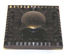
This is an example of a nozzle that fits the Design #1 system. This picture shows the bottom of the nozzle. The cost of this nozzle is about $15.00. It has a 2" male NPT connection. It is injection molded from ABS or polypropylene.
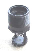
Here is a round pattern nozzle for Design #2. The cost of this nozzle is about $4.00. It has a 1.5" male NPT connection. It is injection molded from polypropylene.
This is a square pattern nozzle for Design #2. The cost of this nozzle is about $4.00. It has a 1.5" male NPT connection or a 1.5" self taping, tapered thread. It is injection molded from polypropylene.
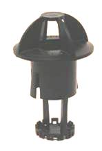
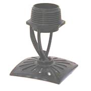
Here is a nozzle for Design #3. This nozzle fits in a hole in a pan. It has a two piece design that locks itself into the pan. Typical spacing is 4 – 12 inches on center, depending on water loading. The cost of this nozzle is about $4.00. It is injection molded from polypropylene.
In order to design a good system, one needs good data. Here is a typical flow vs. pressure chart. This chart allows the designer to choose the number of nozzles that are needed for a given flow at the available pressure. If the flow per nozzle is known, one can determine the head loss through the nozzle. Although the pressure is shown on the X axis, it is the dependent variable.
After the number of nozzles, operating pressure and flow is known, the correct spacing above the media must be determined. A diagram showing water spread is very helpful. Here is a typical example.
Design Example 1
Using the above charts we can design a distribution system for a typical CO2 stripper. The proposed tower has a 4 ft. x 4 ft. plan area and a flow rate of 232 gpm. If we divide the tower into 4 equal squares of 2 ft. x 2 ft. then the flow per nozzle will be 58 gpm. Using the chart for flow vs. pressure we see that a nozzle with an orifice of 1.375 in. will have a pressure loss of 4 ft. H2O. Since the pattern is 2’ x 2’, the distance from the center of nozzle to the edge of pattern is 12”. Using the spread chart for the 1.375” orifice we see that the bottom of the nozzle must be about 9 from the media to get the 12” horizontal spread.
Design Example 2
For this example let us design a pan distribution system. The tower is 4 ft. x 6 ft. plan area. The water flow rate is 200 gpm. If we space the nozzles 8” on center and 8” from the walls there will be 5 rows of 8 nozzles for a total of 40 nozzles. The flow per nozzle will be 5 gpm. Using the chart below there is a choice between two nozzles. The .75 in orifice will require a head of 6 in. of water in the pan. The .875 in orifice will require 3.5 in. of H2O in the pan. The usual vertical spacing for these types of target nozzles is 2- 4 inches from the bottom of the nozzle to the media surface.
Summary
Good water distribution is a critical component of packed towers design. Fortunately, it is relatively easy and inexpensive to do it right. In most cases, it is also possible to retrofit a good system into an existing tower. Consult with your tower or media supplier to improve the performance of your trickling filters and CO2 strippers.
©2006 by L. S. Enterprises.
All rights reserved. No part of this publication may be reproduced or
transmitted in any form or by any means electronic or mechanical, including
photocopy, recording, or any information storage and retrieval system, without
permission in writing from the publisher.
Published by L. S. Enterprises
PO Box 13925
Gainesville,
FL 32604 USA
Author: Matt Smith
Office 1-352-379-5626
Mobile
1-239-851-1175
Fax 1-866-706-1775
Email: mattsmith@biofilters.com
rev. 8/07/2013